Introduction
Equipment
Recordings
Other Stuff
Links
Now that the siren is finished I thought it was time to boost the sound level a bit. Together with a coworker I started designing a class D amplifier for the siren. The obvious reason for choosing a Class D over other types is the efficiency. To deliver 100W peak into the 4 ohm speaker all I need is approximately 24V. The amplifier is set to amplify 24 times. So with a 1V peak on the input you get 24V peak on the output. The amplifier is a self-oscillating type amplifier which was not my first idea...but it worked out pretty good.
The initial idea was to make an amplifier for my siren but it also turned into a semi-hifi project. So we used quality parts for both the input op-amp and comparator. The end result was a great siren amplifier and a semi good hifi amplifier (its a religious subject...so!).
In this video I hooked the siren to the amplifier which is connected to the Whelen SA314. This is very very loud.
And here I hooked the amplifier to my laptop and blasted out some good old music. :)
 |
 |
Back when I was building the police siren I knew that I should make some kind of powerful amplifier. I didn't know much about Class-D amplifiers so I kind of stuck to the typical Class-A / AB / B designs. One of my coworkers is really in to Class-D amplifiers and we started talking about my project. My first idea was to built the amplifier with a triangular waveform generator. But this design included more components then a self-oscillating amplifier.
It was clear from the begining that I would kind of stick to the HIP4081 H-bridge driver. I had already been reading about that approach and liked the AN9525 Intersil application note. From the start it was also a project for my coworker to test out some theories and a challenge to minimize parts-count.
The amplifier ended up with a differential input and a very good op-amp in the input. This section is made up of two OPA2132 with a gain of 3.4 and from there it enters a high speed comparator LT1016 (or TL3016 from Texas Instruments). The audio from the input is made into square waves in the comparator and send to the H-bridge driver. The four MOSFETs are then driven on and off by the HIP4081 and the square audio signal is then "converted" back to audio by the output filter coils and caps. Since this is a self-oscillating amplifier a small part of the output signal is fed back to the comparator. This is done by the four 3k48 resistors (R14-R17) which sets the main amplifier gain to 7 times. This all ends up with a total amplifier gain of 24.
The self-oscillating frequency of the amplifier is set to 385 kHz. This should be set at least 10 times higher then the highest audio frequency you want out. So if you want the amplifier to work in the 20Hz to 20kHz range you need a self-oscillating frequency of at least 200 kHz. Since my sirens highest output frequency is 1500 Hz this was not important for me. But with hifi audio in mind we ended up setting it high.
Capacitor C25 on the audio output and C9-C10 in the feedback loop selects the self-oscillating frequency. I found that if C9-C10 are 470pF you get a "low" frequency of around 250 kHz which was not suited for audio. So they were changed to 220pF and that lifted the frequency up to the 385 kHz.
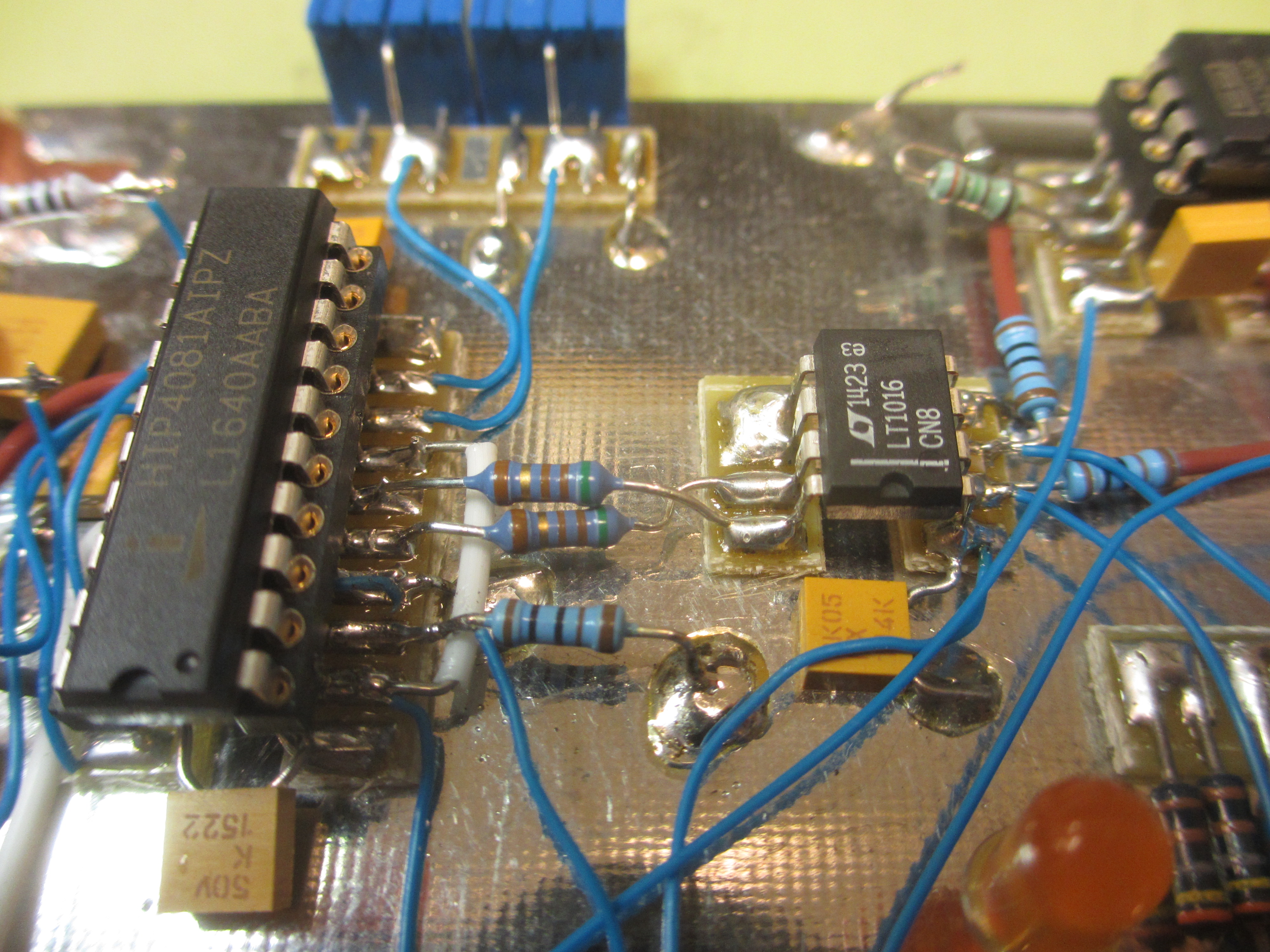
Building the thingSince a Class-D amplifier is a fast switching device it is important to pay attention to layout. Even building it on a ground-plane like I did is not that easy. All the switching parts should be placed as close together as possible and the comparator connection to the H-bridge driver is also critical. To get as low distortion as possible (hifi) you want the squares to be very clean. Even a DIL socket for the LT1016 will introduced distortion which was reduced after removing the socket and soldering the chip closer to the ground-plane. It was also necessary to add resistors R11 and R12 between LT1016 and the HIP4081 to get better control of the signal.
 |
 |
Below you can see that by removing the DIL socket some of the ringing has been removed. If you build this amplifier it would be a good idea to do it with SMD parts.
 |
 |
The choice of MOSFET is also important. They should be fast and have same rise/fall time and have low gate charge. I didn't have to look long for the perfect MOSFET...they were already in my junk-box. The IRFB4019 is specifically design for Class-D audio. The biggest issue was the dreaded DEAD TIME thing...!
In the Intersil Application note the two resistors connected to pin 8 and 9 on the HIP4081 set the dead time. My amplifier worked fine with just two 100k resistors but the MOSFET temperature did rise a little (after playing music for half an hour the temperature reached 35C). I did however try to adjust the values and ended up with 13k9 and 45k5. The amplifier uses less current when the dead time is correctly adjusted but not that much. If you measure the distortion of the amplifier you will see a difference if you haven't adjusted the resistors (again some hifi stuff). For my siren amplifier it did not matter at all.
Adjusting the dead time was done by measuring the voltage on the gate and the drain of the MOSFETs. The light blue waveform is the gate of the lower MOSFET in the H-bridge and the darker blue is the drain in the first screen dump. The second screen dump is the upper MOSFET gate and drain. This was only measured on one half of the H-bridge...we figured it would be about the same on the other side of the bridge.
 |
 |
 |
 |
I most admit that this adjustment was done by my coworker. He could "see" when the signal was just perfect...I COULD NOT. So if you build one of these your signals should look like this.
The Schematics
The schematic: 100W Class D Schematic page 1.pdf
The schematic: 100W Class D Schematic page 2.pdf
I made some measurements on the amplifier and it is actually okay. It is designed for a maximum input of 1Vp which gives a theoretical maximum of 24V on the output. I have made my measurements at 100mVp, 500mVp and 1Vp. At low input levels (100mVp) the THD is actually pretty good about 0.15% but at full input level it rises above 1% which is not that good.
FFT at 100mVp Input
Gain at 100mVp Input
THD+N at 100mVp Input
FFT at 500mVp Input
Gain at 500mVp Input
THD+N at 500mVp Input
FFT at 1000mVp Input
Gain at 1000mVp Input
THD+N at 1000mVp Input
At the moment I'm trying to make a better PCB design using SMD components. I hope this will give the amplifier better specs. But again this was design for my SIREN not for audio.
