Introduction
Equipment
Recordings
Other Stuff
Links
UPDATED
24th of December 2014
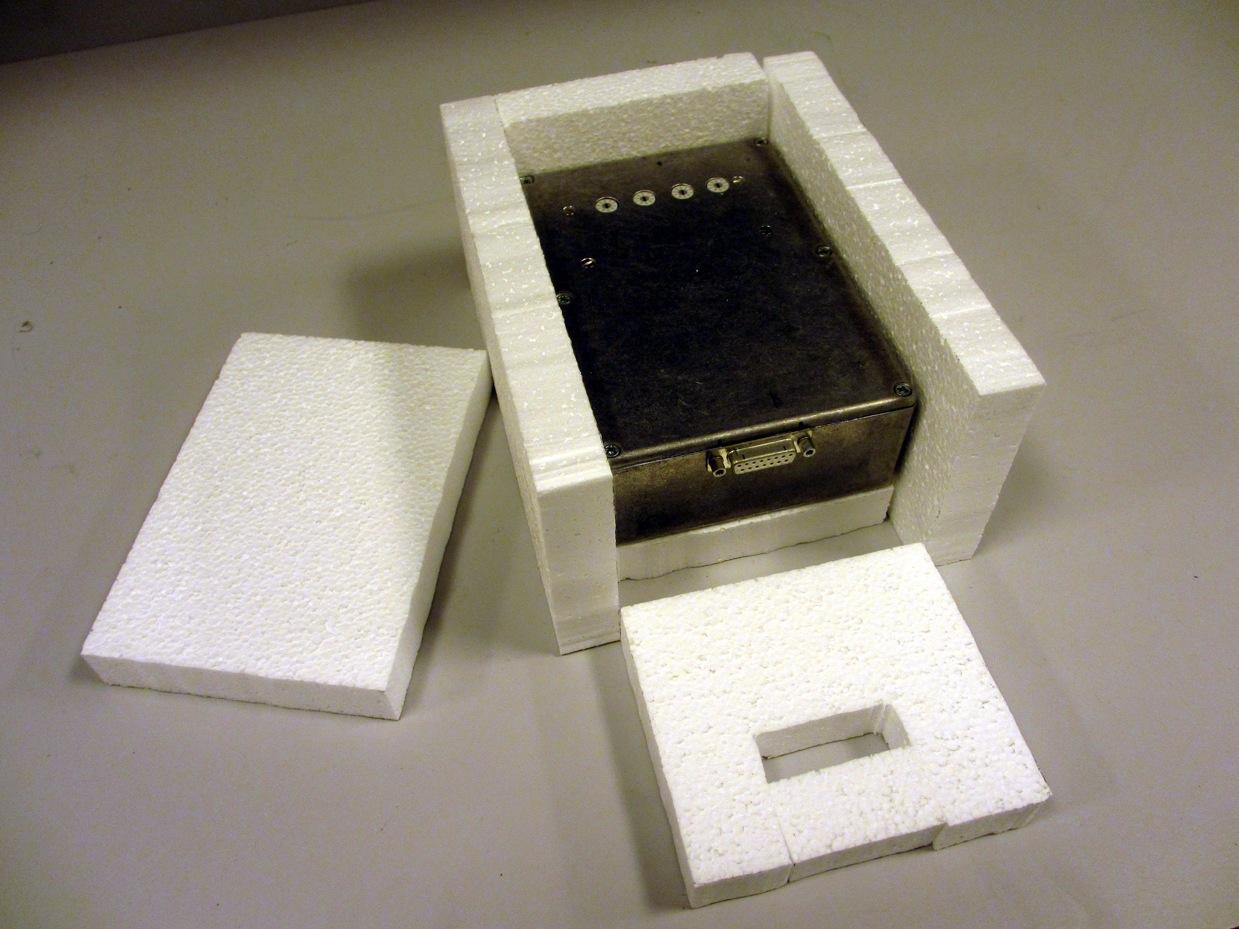
I have finally finished the oven-assembly so now I just need to mount the two pcb's inside the box. At the bottom of the oven-assembly an aluminum plate acts as a heater. I have used 6 resistors and by controlling the voltage and current I can heat the entire box to 57C with 10V 500mA. So it should work fine.
 |
 |
 |
 |
 |
 |
9th of December 2014
At the moment the OpAmp board uses a 14k000 resistor as a SOT resistor. But the finished version will used this PPM-adjust board so that the drift over time can be compensated out. This board will be mounted in the oven with the LTZ board and the OpAmp board. The resistors I used are Holco resistors from TE.
 |
 |
8th of December 2014
After the Siren project I have returned to the 10V Reference project. And I have already changed a lot of things. I decided to drop the linear regulator approach and now I have built the circuit from Application Note 86. So it looks like I ended up where I started by using the LTC1150 + LT1010 design.
 |
 |
 |
 |
In the schematic I have used a 14k000 resistor as a SOT resistors. In the finished version I will still used the BCD resistor network. I have redesigned the BCD resistors network (Fluke's PPM adjust circuit)...more on that later.
24th of May
Over the past few days I have had some difficulties getting my 7-to-10 amplifier to work correctly. The original idea was a simple linear regulator design using a NPN transistor and an OpAmp wired as a comparator. This works great with a low-gain device like a 2N2222A transistor...but if you switch to a MOSFET its a whole new set of problems you run into.
I learned that the original NPN design worked great with no load on the output. So I moved on to test the current limit circuit (R6, Q2) and found that the output voltage would drop at least 100uV if the output was loaded. I tried to load the output in the range from 1mA to 10mA and found that no change in output voltage occured if the load did not exceed 2mA...and this is just not good enough.
I figured that the I could change R7 to 100R from the original 1k00...but it had little effect. Now the drop was about 70uV and if I shorted resistors R7 it did not change the 70uV drop. So I figured I would try to use a MOSFET since it has higher gain.
Using a MOSFET most be simple I figured...and in LT Spice it worked fine (when I did an DC Operating Point simulation). I failed to do an AC analysis of the circuit. And when I build it in the lab it was not working as I had hope for. The output voltage was 11.2V and putting an oscilloscope on the output did not make me happy. It was oscillating like crazy and it did not help to distribute capacitors around the board.
Since my colleagues are very familiar with Cadence PSpice they were able to help me out. In the end it took some time to get it right but now it is working great.
 |
 |
My attention has now moved to the Resistor board. I have decided to make this into a seperate board and reduce the number of resistors. I will also be looking into making a better PCB layout for the OpAmp board.
18th of May
Since last I have learned that burn-in is a very good idea...and I must say that I am pleased with the results. I decided to give the LTZ board an extra 300+ hours at 65C. As I raised the temperature I could see the output voltage varying like crazy...and it stopped at 7.18810V where it stayed for the 300 hour duration. The output voltage returned to 7.18173V after I lowered the temperature to 50...40...and 30. And at 25 it was stable even when I raised the temperature back to 65C the output was rock-stable at 7.18173V.
I was not sure my 7-to-10 volt amplifier would work as well as it actually did. The "SOT" resistor network actually works very nicely. The output voltage can this way be fine-tuned with the BCD switches. The output is a little unstable in the 10 uV range...but I really think this stability problem will disappear after this board is burned-in.
 |
 |
 |
 |
I have one small issue I need to look at...the output current. I have set the max output current to ca. 10 mA...but even with light loads (5 mA) the output voltage drops 5 uV. I may need to change the base resistor...or change the whole output circuit to a MOSFET output. But nothing has been decided yet. :)
Another very important finding is that I can lower the supply voltage to the LTZ board to 11.5V without any change to the output. This is a very handy thing since I can now run the entire circuit from a 12V battery. The LTZ board works all the way down to 8.8V supply...I do however not know if the output will be more noisy. I figured the only part of the circuit that could be a problem was the heater transistor...but it seems to be working fine even at 65C.
Here are the current schematics:
OpAmpResistorBoard (RevA1)
HeaterControlBoard (Rev6)
22nd of April
The project has not been moving at all for a while...but now it is moving again. I have tested my heater board and found that it is not as good as I had hoped for. In the thermal image it is pretty clear that the heat does not distribute evenly on the board. At the moment I am re-designing it so that more heat will be disipated along the edge of the PCB. I hope that this will remove the "pyramid" shape heat pattern and get a more even heat distribution.
 |
 |
 |
I found that the temperature inside my enclosure was easy to control. By controlling the amount of power dissipated in the resistors I was able to get as high as 48C. A small graph can be seen here. By applying 15V to the 88R resistor the temperature inside the box could get to 35C so I decided to change the resistors to 44R. With this new value I could reach 48C with an ambient temperature of 22C. The red curve is 44R and the blue 88R and the power dissipated in the resistors are 2.54W and 5.04W. And of course the Y axis is the temperature in Celcius and the X axis is time.
Here is the schematic idea for the heater controller. Instead of having a thermostat that keeps turning on and off the heater element (and generating noise) I am doing something else. By controlling the amount of power delivered to the resistor board there will not be noise from turning the heater on and off.
At the moment the LTZ board is undergoing a little extra burn-in. After reading up on the burn-in I decided to give my board some extra cycles. Because I use mainly commercial parts I can not go higher then 65C. But it is better than nothing.
3rd of March
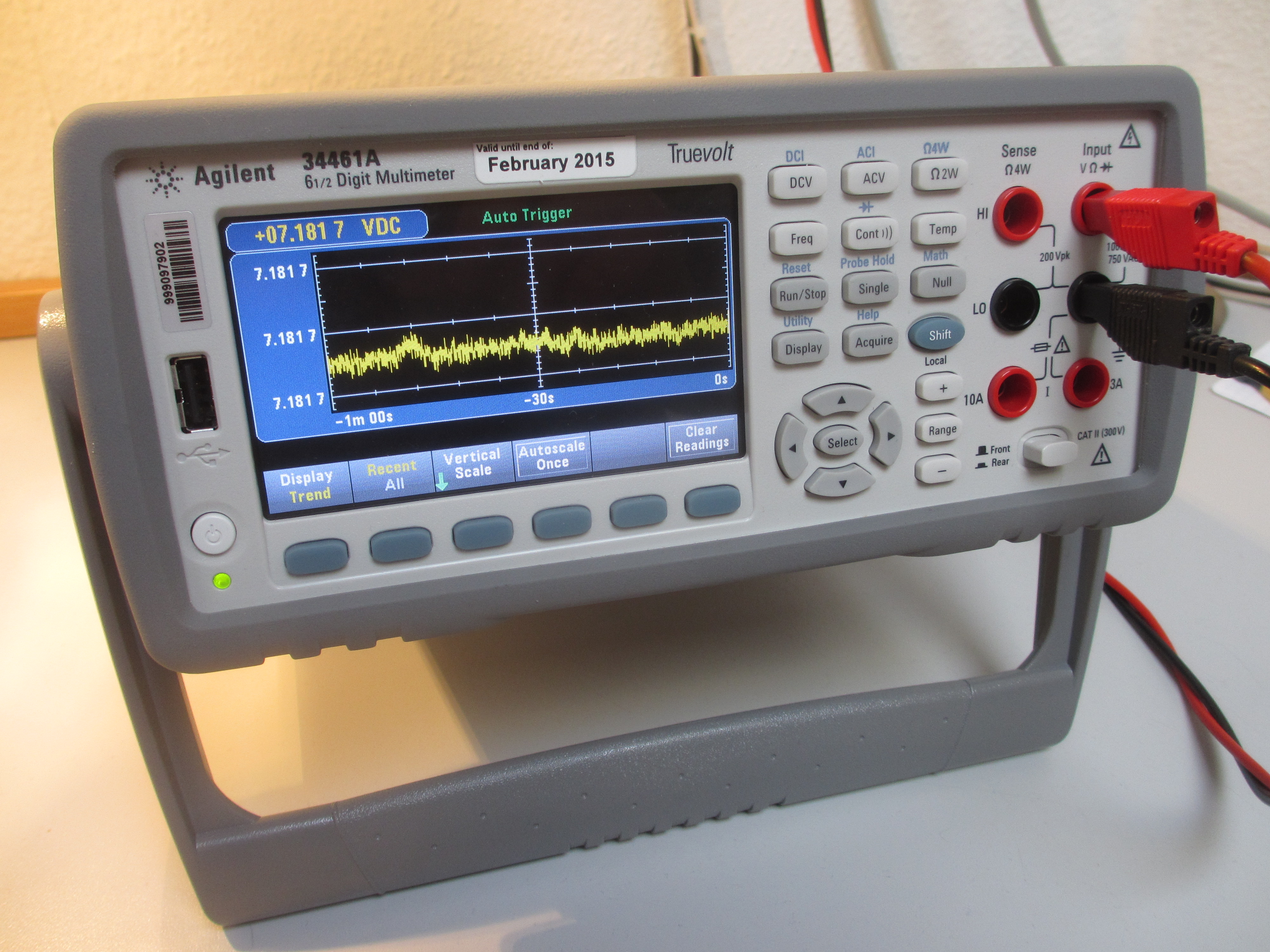
The 1000 hour burn-in test has now been completed. In the process I tested the "new" Agilent 34461A DMM. This is a nice a meter and I recommend watching the review that Dave Jones made on YouTube. I also got a chance to test my 8� digit Solartron 7081 DMM. The meter is a bit off compared to all other DMMs that I used with the LTZ-1000A board. So it will probably need a fresh calibration soon.
 |
 |
Next I will make the heater control board. More will follow...
2nd of February
I have made a preliminary schematic of the basic idea of this 10V reference. The OpAmp has been changed to the LTC1051 chopper amp.
 |
 |
Some weeks ago I started the 1000 hour burn-in of the LTZ1000A board. As can be seen the output at the moment is a steady 7.18182 volts. It changes to 7.18181 volts if the temperature in the room drops. Maybe I should have made the burn in inside the ovenized box...but the design of the oven is not done yet.
To be able to trim the 10V out I am trying the BCD trick used by Fluke (see page 2 of my schematic). I must say that I found the manual for the Fluke 732B very helpful and informative. And on the EEVBLOG some guy made a teardown of his Fluke 732B...nice. :)
16th of January
Today I finally got around to building the LTZ reference board. Some days ago I received the PCBs from ExpressPCB in California. I must say that I'm very pleased with the results. The PCBs are high quality and the software from ExpressPCB is very easy to use.

I decided to go with the schematic from Linear Tech's own Application Notes (App Note 86). But I did change some minor things like the transistor for the heater and 22nF cap was also changed. The complete schematic that I used can be found here.
The schematic symbol for the LTZ1000A in Linear Tech's own datasheet and the App Note is pretty confusing. In an old manual for the Datron 4910/4911 I found a much better symbol that I used instead. Some other things I did was add a 100uF cap near the heater power line. It may reduce the noise when the heater switches on and off. C1 in the original schematic was set to 22nF and I changed it to 100nF and transistor 2N3904 was changed to a 2N2222A. Resistors R6, R7 and R8 are standard 1% metal film resistors and R1, R2, R3, R4 and R5 are all RNC90Y precision resistors. Since I did not have two 70k000 resistors I had to put a few values I had in series. A 10k100 + 10k000 + 49k900 = 70k000. And last R9 (a short) was needed so that I could get single-point grounding.
The final result can be seen here. The voltage out is 7.18178V and T(amb) is 21C.


The next step is burn-in of the LTZ1000A which should be around 1000 hours. After that the output voltage should be as stable as it gets. The idea is to complete the 1000 hours in the temperature controlled enclosure. At the moment I am building the heater control circuit which I will set to 35C.
I have made a couple of changes to my original LTZ1000A reference idea. The PCB will look like this and the idea is to mount it inside a temperature controlled enclosure. A proto type of the heater board can be seen in the picture. Even though the reference is inside a metal can I am going to cut away some of the PCB around the reference. According to Linear Technology the metal can should be immune to board stress...so it is a bit overkill. To minimize noise from the heater switching on and off the heater wires are kept away from the reference circuit.

Since I did not have 70k000 resistors (R2a-b-c and R3a-b-c) I had to add some of my precision resistors. I have decided to order the board from ExpressPCB for the first time (I have used them at work). It is not cheap whene you live outside the US...but hey. :)
The LTZ1000A reference board is mounted inside the temperature controlled enclosure with the amplifier board. The amplfier boost the 7.2V to 10.0000000000000000V (I wish) which is then accessible on the front of the finished reference box. I have also decided not to use the LT1010 buffer but instead build the output as a serie regulator. I will still be using the LTC1150 chopper Op Amp. At the moment I am trying to add a battery circuit so that it will never loss power. The temperature control will be something with a LM35 or maybe a PT100 (or PT1000).

Since I build my first reference based on the LM299 I figured why not try the LTZ1000A. I will try to make a better reference this time. I will be using a chopper stabilized Op Amp (LTC1150) and a buffer (LT1010) as specified in Linear Technology Application Note 86. The specific part of the App Note can be found here.

The output amplifier that boosts the 7.2V to 10V needs precision components to achieve low temperature coefficient. I should be able to get some kind of resistor network made from my many RNC90 and RS92N resistors. In the Fluke 732B DC Reference Standard they use a resistor network with BCD switches. See here.